Resistance Spot Welding (RSW) is the preferred method for attaching of panels and should be used whenever possible.
This bulletin indicates where spot welding is practical in repair conditions using portable resistance spot welding equipment.
One repair weld shall be added for each spot weld being repaired, by using either a resistance spot weld or a plug weld, subject to the applicable Holden authorised repair procedure.
Resistance spot welding is faster, and more efficient than plug welding. It reduces rust formation and heat distortion occurrences, limiting the amount of refinishing required.
MIG welding should be used for plug welding and also for fusion welding when required, as per Holden’s authorised repair procedures.
Where resistance spot welding equipment is not available, or it will not access the required weld position, a plug weld must be performed.
Gas welding (oxy/acetylene welding) should be avoided as a method of panel attachment.
The heat generated when creating a fused joint causes a decline in the strength of the areas and panels surrounding the welded parts, and also introduces a high possibility of warping.
Holden recommends all weld methods be performed by trained Tradesman/Technicians, to ensure weld integrity of collision repairs.
CAUTION 1: Always take care when welding. Look behind the parts and the surrounding location being welded to avoid additional damage or possible fire.
CAUTION 2: Flammable materials are used in the vehicle, always take care to avoid fire when welding.
CAUTION 3: Battery disconnection must be performed before any welding method is conducted.
CAUTION 4: When performing MIG welding, the earthing lead must be located as close as possible to the weld area, with minimal lead contact to the vehicle as possible.
RESISTANCE SPOT WELDING (RSW)
Resistance spot welding is a method of fusing metal parts together.
Pieces of metal sheets are positioned between two electrodes (weld tips) where pressure and a large current are applied.
Due to electrical resistance of the metals, a large amount of heat is locally generated causing the metals to fuse together.
Resistance Spot Welders
1. The resistance spot welding machine should be adjusted using the minimum length of the arm appropriate to the particular weld, location, so that the maximum clamping pressure is available.
2. The electrode tips should be aligned to be parallel and on the same axis to maintain maximum pressure and weld alignment.
3. The correct welding tips should be employed.
4. Single sided spot welding must not be performed.
Panel condition
1. The panel surface must be free of paint film, rust, dirt and other contaminates so that current flow will be sufficient for proper fusion.
2. All mating surfaces must be treated with a weld through primer to prevent corrosion in this inaccessible area. The correct primer has high conductivity to facilitate the weld.
3. The mating surfaces must be prepared so that there are no gaps between panel surfaces. Weld condition is considerably reduced by poor contact and reduced current flow.
Number of welds
1. The same number and similar position of resistance spot welds should be used when replacing the panel, as was used during manufacture, if specified in the Holden authorised repair procedure.It is important to maintain the original structure of the strength of the vehicle, particularly because of the implications in deployment of the SRS system.
2. Spot welding too closely spaced weakens the welds due to the shunt effect of the current. Apply a non-sequential welding procedure. As a general rule, welds should not have less than 25mm of space between them.
GM Recommended Resistance Spot Welders
The following Resistance Spot Welding machines are recommended by GM as of March 2017.

Weld testing
1. Prior to welding; pieces of the same thickness and material panel, as required for repair, should be welded together as a test., using the intended welding settings. The weld should then be destroyed by twisting the pieces. If the settings are correct, there should be a weld button (nugget) pulled out of one test piece. If not, the weld settings must be adjusted and test repeated, until a successful weld nugget is produced.
2. Completed weld sections may be tested using a hammer and chisel (or flat bladed screwdriver). The testing should cease once the size of the weld nugget can be determined, and the welds are still intact.
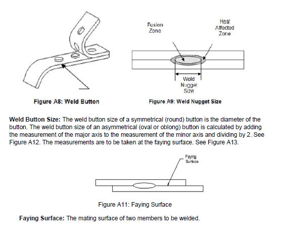
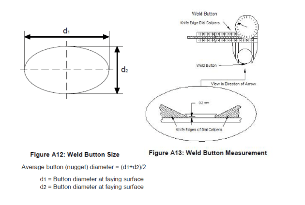
3. The weld size may be measured by either using the weld button (Figure A8) or the weld nugget (Figure A9). A resistance spot weld is unacceptable when the measured weld size at the faying surface (Figure A11) is less than the acceptable minimum nugget weld size of 4.0mm.
4. An evaluation of the welding area is required. It must be free of tempering colours, staining, depressed foreign metal particles, holes, cracks and weld spatter.
A successful resistant spot weld imprint should be brown in colour inside and outside with an outer blue ring. The weld point indentation should be no more than 20% of the respective sheet thickness.
5. In addition to the coupon testing described above, the weld evaluation that is performed in step #4. must also be conducted for the resistance spot welds performed during vehicle collision repair.